|
Self Supporting Towers <Tower Sizing Chart>
Guyed Towers |
|
CHOOSING THE TITAN™ TOWER FOR YOUR APPLICATION The Tower Sizing Charts below are a quick-reference guide for selecting the right Titan tower for your application. Follow the 3 steps listed below the chart to select the appropriate tower model.
|
|
Chart 1: No Ice Scenario |
|
Chart 2: 1/2” Radical Ice Scenario |
|
STEP 1: Determine maximum local wind strength
The maximum wind speed is defined as the maximum "3 second gust" experienced in the area, typically over the past 30 or 40 year period. Once you've determined the wind speed in your area, select the corresponding column in the Tower Sizing Charts. |
|
STEP 2a: Determine the Projected Surface Area of Your Antenna Load Find out the square foot surface area of each antenna for wind loading purposes. This figure is usually available from the manufacturer's spec sheets. If not shown on their spec sheets, phone the manufacturer and ask to speak to an engineer. Also find out whether the load is a round/cylindrical surface or a flat plate surface. This is important because flat plate equivalent surfaces cause greater wind loading.
|
|
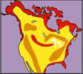
Important Notes: If you don't know the wind speed, consult your local weather office. Other sources may be your local building authority or building codes.This map of North America provides only representative wind zones and should not be used as a substitute for verified data. Red = 100 mph Orange = 85 mph Yellow= 70 mph . The wind speeds shown in sizing Chart 1 above are with NO ICE! If radial ice accumulation occurs, then the allowable antenna areas shown will be reduced - see Chart 2 above. |
|
Note: sometimes antenna manufacturer's will provide projected surface area of a "round" antenna as a flat plate equivalent.
Other terms for projected area include: · Flat Plate · F.P.E. · Wind Load Area · Wind Load (s.f.) · Antenna Area · Area · Exposed Area · Bare Area |
|
OR
STEP 2b: Determine the Maximum Horizontal Wind Thrust of Your Load
On occasion, antenna manufacturers may provide a horizontal thrust (or lateral thrust) instead of the projected area. This figure is usually available from the antenna manufacturer and is expressed in lbs. If antenna spec sheet shows neither a projected surface area nor a horizontal thrust figure, contact the antenna manufacturer.
STEP 3: Determine the Ice Loading for the Tower Site
Ice accumulation for the area where the tower will be erected is an important factor, and should be verified before you determine the allowable antenna capacity for your tower. Some areas have no ice accumulation (if your area has no ice accumulation, please reference Chart 1) while other areas may have ice accumulation of 1/2" (if your area has 1/2" of ice accumulation, please reference Chart 2).
If you don't know the ice accumulation, consult your local weather office. Other sources may be your local building authority or building codes. Once you've determined the ice accumulation in your area, select the corresponding column in the Tower Sizing Charts above.
STEP 4: Find a Match on the Tower Sizing Chart
With both the local wind speed and sq.ft. surface area (or horizontal thrust) in hand, simply look up the column in the Tower Sizing Charts which sufficiently matches your numbers. If your wind speed and projected surface area fall within the maximums stated, then you have found a match. Finally follow the row to the left to determine the tower height and Titan model.
Important notes: Figures shown in the Tower Sizing Charts represent the MAXIMUM wind thrust that the tower can survive in the designated wind zones, centered at 3 ft. or less above the tower top
Allowable antenna areas shown in tower sizing chart 1 are based on NO radial ice occurrence. The allowable antenna areas shown in tower sizing chart 2 are based on 1/2" radial ice.
The wind thrust values shown in the Tower Sizing Charts represents the MAXIMUM wind thrust that the tower can survive n the designated wind zones, centered at 3 ft. or less above the tower top.
The projected surface areas listed in the charts represent the maximum allowable antenna area that the tower can survive, centered at 3 ft. or less above the tower top. Maximum antenna weight (or vertical force) supported at the tower top should not exceed 300 lbs, and must be centrally located and balanced over the tower cross-section.
When supporting the maximum horizontal and vertical forces noted above, the minimum safety factor in the weakest tower component would be 1.0. Exceeding the indicated maximum loads could result in tower failure. Consult the factory on unusual applications. |